———————————- UPDATE ————————————–
For a ADC Input Frontend with Auto-range capabilities in the 0-40V Input range take a look also at the new ADC Input related article
——————————— UPADTE —————————————-
After testing the ESP8266 Internal ADC I think it’s time to see also a higher resolution ADC at work. For this project we will use Microchip MCP3421 I2C ADC.
The MCP3421 is a single channel, low-noise, high accuracy delta-sigma A/D converter with differential inputs and up to 18 bits of resolution in a small SOT-23-6 package. The on-board precision 2.048V reference voltage enables an input range of ±2.048V differentially.
The device uses a two-wire I2C compatible serial interface and operates from a single power supply ranging from 2.7V to 5.5V.
This device has an onboard programmable gain amplifier (PGA). User can select the PGA gain of x1, x2, x4, or x8 before the analog-to-digital conversion takes place. This allows the MCP3421 device to convert a smaller input signal with high resolution.
The device has two possible to configure conversion modes:
- Continuous mode
- One-Shot mode.
In One-Shot mode, the device enters a low current standby mode automatically after one conversion. This reduces current consumption greatly during idle periods. Very goob for low power battery powered applications.
FEATURES:
-
- 18-bit resolution
- Small 6-lead SOT-23 packaging
- Differential input operation
- On-board voltage reference with 5 ppm/°C drift
- On-board PGA, gains of 1, 2, 4, 8
- Programmable data rate options
- 3.75 SPS (18 bits)
- 15 SPS (16 bits)
- 60 SPS (14 bits)
- 240 SPS (12 bits)
- INL 10 ppm of FSR max
- Low current consumption, 145 µA at 3V
- One-shot or continuous conversion options
- Supports I2C™ serial interface
- Extended temperature range: -40°C to +125°C
For more details, please see MCP3421 Datasheet
As been available in SOT-23-6 package, we will use again an DIP adaptor that will make it easy to integrate it on our CBDB Board expansion slots:
 |
|
| MCP3421 – SOT-23-6 To DIP Adapter |
Our CBDB Board has started to evolve and develop nice, with some interesting functions on board:
- 12 Bit DAC
- Selectable 12-14-16-18 Bit ADC
- RTC
- High Precision Temperature sensor
- Expansion slot for PIR sensor / Triac Main Power Switch module or anything else you want
- LCD
- Programming port – USB Adapter

Because of the high interest and the number of requests raised by the CBDB project in the next weeks we will run small batches of CBDB based devboard PCBs. The main purpose of the CBDB board was for local training and drivers development but if any new one interested please express your wishes at: tech at esp8266-projects.com.
It will be nothing fancy, just CBDB Board + some extra goodies on a standard 2 side factory made PCB that can help you to connect in minutes a new module and start programming. A nice I2C Dev Board, KISS concept at its plenitude :). A related Article will follow as soon as the first ones will hit the MailBox.
 |
| CBDB DevBoard v2.0b |
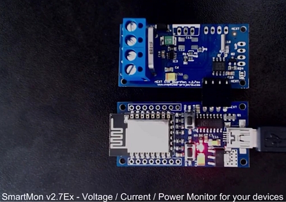
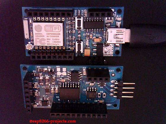
What we will need for our ADC project:
- CBDB Board
- USB adapter (take a look on Part 1 for details how to connect them together)
- MCP3421 Module from above
- Battery Module
- Voltage divider
- LCD Display
MCP3421 ADC I2C Driver implementation
As MCP3421 has a I2C compatible compatible interface, driver building it following more or less the same process as before for I2C devices.
Few important consideration about MCP3421:
– The MCP3421 has an 8-bit wide configuration register to select for: PGA gain, conversion rate, and conversion mode. This register allows the user to change the operating condition of the device and check the status of the device operation. The user can rewrite the configuration byte any time during the device operation.
– The MCP3421 device accepts a fully differential analog input signal which is connected on the VIN+ and VINinput pins. The differential voltage that is converted is defined by VIN = (VIN+ – VIN-) where VIN+ is the voltage applied at the VIN+ pin and VIN- is the voltage applied at the VIN- pin.
– The input signal level is amplified by the programmable gain amplifier (PGA) before the conversion.
– The digital output code produced by the MCP3421 is a function of PGA gain, input signal, and internal reference voltage. In a fixed setting, the digital output code is proportional to the voltage difference between the two analog inputs.
– The output data format is a binary two’s complement.
With this code scheme, the MSB can be considered a sign indicator. When the MSB is a logic ‘0’, it indicates a positive value. When the MSB is a logic ‘1’, it
indicates a negative value. The following is an example of the output code:
- for a negative full-scale input voltage: 100…000
- for a zero differential input voltage: 000…000
- for a positive full-scale input voltage: 011…111.
The MSB is always transmitted first through the serial port. The number of data bits for each conversion is 18, 16, 14, or 12 bits depending on the conversion mode selection.
LSB size vs. conversion mode set :
Bit Resolutions LSB (V)
12 bits 1 mV
14 bits 250 μV
16 bits 62.5 μV
18 bits 15.625 μV
For programming and uploading the driver and the software we will continue to use the LuaUploader as before.
1. Init I2C bus/interface
          init = function (self, sda, scl)
                i2c.setup(0x0, sda, scl, i2c.SLOW)
          end
2. Write ADC Register Function
        write_ADC_config = function ( self, dev_addr, set)
               i2c.start(0x0)
               i2c.address(0x0, dev_addr ,i2c.TRANSMITTER)
               i2c.write(0x0,set)
               i2c.stop(0x0)
          end
3. READ ADC Function – 12, 14, or 16 bit-mode, 0-2.048V Range
       read_ADC_data = function (self,dev_addr)
              i2c.start(0x0)
              i2c.address(0x0, dev_addr,i2c.RECEIVER)
              c = i2c.read(0x0,3)
              i2c.stop(0x0)
              vadc = (bit.lshift(string.byte(c, 1), 8) + string.byte(c, 2))
              return vadc
          end
For testing, pack it together and save the code on ESP as ‘mcp3421.lua‘, restart ESP and run:
        require('mcp3421')                                         -- call for new created MCP3421 Module Driver
         sda=2 --GPIO4
        scl=1 --GPIO5
        mcp3421:init(sda, scl)                                    -- init I2C
        mcp3421:write_ADC_config(0x68, 0x10)     -- Write Register config: 12Bit/CCV/PGA = 1V/V
        adc_val = mcp3421:read_ADC_data(0x68) -- Read ADC Data

        print("ADC Value : "..adc_val)

        lsb=1         -- 12 bit -> LSB = 1mA

        vts = (adc_val * l1)/1000*4.3043     --calibrate based on your power supply, Vref and divider

        print("\nValue = " ..adc_val.." \nVolts = "..string.format("%g",vts).." mV")
        print("\nValue = " ..adc_val.." \nVolts = "..string.format("%.4f",vts).." mV")
 |
| MCP3421 ADC – First test |
First Test Video – Noisy environment – Live Bus voltage:
Filtered clean source voltage measurement
4. Read ADC and Print values on LCD
       read_ADC_LCD1 = function()
            adc_val = mcp3421:read_ADC_data(0x68)
            l1=1         -- 12 bit
            --l1=0.0625    -- 16 bit
           val = (adc_val * l1)/1000*4.3043
           print("    ReadADC     : "..val)
           val = string.format("%g",val)
           st7032i:lcd_print(0,2,adc_val)
           st7032i:lcd_print(9,2,val)
       end
For testing, pack it together and save the code on ESP as ‘mcp3421.lua‘, restart ESP and run
       require('mcp3421')                                         -- call for new created MCP3421 Module Driver
         sda=2 --GPIO4
        scl=1 --GPIO5
        mcp3421:init(sda, scl)                                    -- init I2C
        mcp3421:write_ADC_config(0x68, 0x10)     -- Write Register config: 12Bit/CCV/PGA = 1V/V
         require('st7032i')
        st7032i:init_LCD()

        st7032i:lcd_setCursor(0,1)
        st7032i:lcd_write("ADC_Val  Volts")

        tmr.alarm(0, 1000, 1, function() read_ADC_LCD1() end)  -- read ADC and Print on LCD
 |
| MCP3421 ADC – LCD Print test |
 |
| MCP3421 ADC – LCD Print test |
1. Test done in filtered environment – highly stable voltage