First RUN test for MAX7219 LED Display Module using ESP8266 CBDBv2 EVO Board

The MAX7219 are compact, serial input/output common-cathode display drivers that interface microprocessors (µPs) to 7-segment numeric LED displays of up to 8 digits, bar-graph displays, or 64 individual LEDs. Included on-chip are a BCD code-B decoder, multiplex scan circuitry, segment and digit drivers, and an 8×8 static RAM that stores each digit. Only one external resistor is required to set the segment current for all LEDs.
A convenient 4-wire serial interface connects to all common µPs. Individual digits may be addressed and updated without rewriting the entire display. The MAX7219 also allow the user to select code-B decoding or no-decode for each digit.
The devices include a 150µA low-power shutdown mode, analog and digital brightness control, a scan-limit register that allows the user to display from 1 to 8 digits, and a test mode that forces all LEDs on.
Key Features
- 10MHz Serial Interface
- Individual LED Segment Control
- Decode/No-Decode Digit Selection
- 150µA Low-Power Shutdown (Data Retained)
- Digital and Analog Brightness Control
- Display Blanked on Power-Up
- Drive Common-Cathode LED Display
- 24-Pin DIP and SO Packages
 |
| Typical Application Circuit |
This is a 5V operation device. If you need to run it by the book at 3.3V Logic Level you will need to use a level shifter. In practice, as you will see below, you can try and run it directly, a bit out of spec. As MAX7219 HIGH logic level is at 3.5V…well…looks like it’s working quite OK also in this way, in 48 hours of continuous running no freeze or strange behaviour:)
For more details please see MAX7219 Datasheet
For a true native 3V operation or segment blinking, take also look to the MAX6951 datasheet.
What we will need:
- CBDB Board ( or any other ESP8266 Board you may like )
- USB adapter (take a look on Part 1 for details about the USB Adapter)
- MAX7219 – 8 Digit Display module
- Connection wires – various colors
- Bench Power Supply – for +5V
- For programming and uploading the driver and the software we will continue to use the LuaUploader as before.
 |
| MAX7219 – CBDBv2 EVO Connection |
Wire MAX7219 ESP8266
Green +5Vcc
Blue GND GND
Yellow DIN 13
White CS 12
Orange CLK 14
MAX7219 Driver Implementation
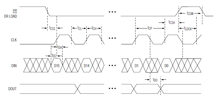
Timing Diagram
Initial Power-Up
On initial power-up, all control registers are reset, the display is blanked, and the MAX7219 enter shutdown mode.
Program the display driver prior to display use. Otherwise, it will initially be set to scan one digit, it will not decode data in the data registers, and the intensity register will be set to its minimum value.
Shutdown Mode
When the MAX7219 is in shutdown mode, the scan oscillator is halted, all segment current sources are pulled to ground, and all digit drivers are pulled to V+, thereby blanking the display.
- Data in the digit and control registers remains unaltered.
- Shutdown can be used to save power or as an alarm to flash the display by successively entering and leaving shutdown mode.
- For minimum supply current in shutdown mode, logic inputs should be at ground or V+ (CMOS-logic levels).
- Typically, it takes less than 250μs for the MAX7219 to leave shutdown mode.
A nice thing is the fact that the display driver can be programmed while in shutdown mode, and shutdown mode can be overridden by the display-test function.
Serial-Addressing Modes
For the MAX7219, serial data at DIN, sent in 16-bit packets, is shifted into the internal 16-bit shift register with each rising edge of CLK regardless of the state of LOAD. For the MAX7221, CS must be low to clock data in or out. The data is then latched into either the digit or control registers on the rising edge of LOAD/CS.
LOAD/CS must go high concurrently with or after the 16th rising clock edge, but before the next rising clock edge or data will be lost. Data at DIN is propagated through the shift register and appears at DOUT 16.5 clock cycles later.
Data is clocked out on the falling edge of CLK.
Data bits are labeled D0–D15.
D8–D11 contain the register address.
D0–D7 contain the data, and D12–D15 are “don’t care” bits.
The first received is D15, the most significant bit (MSB).

Digit and Control Registers
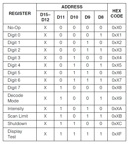
14 addressable digit and control registers.
The control registers consist of decode mode, display intensity, scan limit(number of scanned digits), shutdown, and display test (all LEDs on).
Decode-Mode Register
The decode-mode register sets BCD code B (0-9, E, H, L, P, and -) or no-decode operation for each digit.
Each bit in the register corresponds to one digit.
A logic high selects code B decoding while logic low bypasses the decoder.

When the code B decode mode is used, the decoder looks only at the lower nibble of the data in the digit registers (D3–D0), disregarding bits D4–D6. D7, which sets the decimal point (SEG DP), is independent of the decoder and is positive logic (D7 = 1 turns the decimal point on).

When no-decode is selected, data bits D7–D0 correspond to the segment lines of the MAX7219/MAX7221.

Intensity Control and Interdigit Blanking
The MAX7219 allow display brightness to be controlled with an external resistor (RSET) connected between V+ and ISET.
The peak current sourced from the segment drivers is nominally 100 times the current entering ISET.
This resistor can either be fixed or variable to allow brightness adjustment from the front panel.
Its minimum value should be 9.53kΩ, which typically sets the segment current at 40mA.
Display brightness can also be controlled digitally by using the intensity register.
Digital control of display brightness is provided by an internal pulse-width modulator, which is controlled by the lower nibble of the intensity register.
The modulator scales the average segment current in 16 steps from a maximum of 31/32 down to 1/32 of the peak current set by RSET.
The minimum interdigit blanking time is set to 1/32 of a cycle.

Scan-Limit Register
The scan-limit register sets how many digits are displayed, from 1 to 8.
They are displayed in a multiplexed manner with a typical display scan rate of 800Hz with 8 digits displayed.
If fewer digits are displayed, the scan rate is 8fOSC/N, where N is the number of digits scanned.
Since the number of scanned digits affects the display brightness, the scan-limit register should not be used to blank portions of the display (such as leading zero suppression).

Display-Test Register
The display-test register operates in two modes: normal and display test. Display-test mode turns all LEDs on by overriding, but not altering, all controls and digit registers(including the shutdown register).
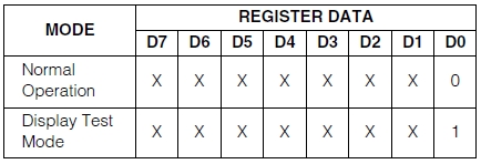
In display-test mode, 8 digits are scanned and the duty cycle is 31/32Software
1. Init
-- MAX7219 registers
MAXREG_DECODEMODE = 0x09
MAXREG_INTENSITY  = 0x0a
MAXREG_SCANLIMIT  = 0x0b
MAXREG_SHUTDOWN   = 0x0c
MAXREG_DISPTEST   = 0x0f

 DIN   = 7      -- 13 - data in pin
CS    = 6      -- 12 - load (CS) pin
CLK   = 5      -- 14 - clock pin

gpio.mode(DIN,gpio.OUTPUT)
gpio.mode(CS,gpio.OUTPUT)
gpio.mode(CLK,gpio.OUTPUT)
2. Write serialised data
function wrByte(data)
   i=8
   while (i>0)
   do
       mask = bit.lshift(0x01,i-1)
       --print(mask)
       gpio.write( CLK, 0)    -- tick
       dser = bit.band(data,mask)
       if (dser > 0)
         then gpio.write(DIN, 1)   -- send 1
              --print("1")
         else gpio.write(DIN, 0)   -- send 0
              --print("0")
       end --endif
       --print(dser)
       gpio.write( CLK, 1)    -- tick
       i=i-1
    end --while
end
3. Set Register
function setReg(reg, value)
  gpio.write(CS, 0)

  wrByte(reg)   -- specify register
  tmr.delay(10)
  wrByte(value) -- send data

  gpio.write(CS, 0)
  --tmr.delay(10)
  gpio.write(CS, 1)
end
4. Convert anf Print integer number in xxxx format
function print_led_int(c)
   th = string.format("%d",c / 1000)
   h = string.format("%d",(c-th*1000) / 100)
   t = string.format("%d", (c-th*1000-h*100) / 10)
   u = string.format("%d", c-th*1000-h*100-t*10)
   --print(string.format("%d %d %d %d", th,h,t,u))
   setReg(4, th)
   setReg(3, h)
   setReg(2, t)
   setReg(1, u)
end
5. Create a Display ‘ZERO’ init stage
function zero_all()
   v=1
   while (v<9) do
       setReg(v,0)
    v=v+1
   end
end
6. MAX7219 Initialisation
setReg(MAXREG_SCANLIMIT, 0x07)
tmr.delay(100)
setReg(MAXREG_DECODEMODE, 0xFF)    -- full decode mode BCD
tmr.delay(100)
setReg(MAXREG_SHUTDOWN, 0x01)          -- not in shutdown mode
tmr.delay(100)
setReg(MAXREG_DISPTEST, 0x00)              -- no display test
tmr.delay(100)
setReg(MAXREG_INTENSITY, 0x00)            -- set Brightness
zero_all()                                                        -- set all to ZERO
7. Test Display – 9999 counter
count=0
tmr.alarm(0,1000,1,
   function()
       count=count+1;
       --print(count);
       print_led_int(count)
       if (count>9999) then count=0;zero_all()
       end
   end)